Hotop Silicone Hose


Silicone Air Intake Systems Solutions
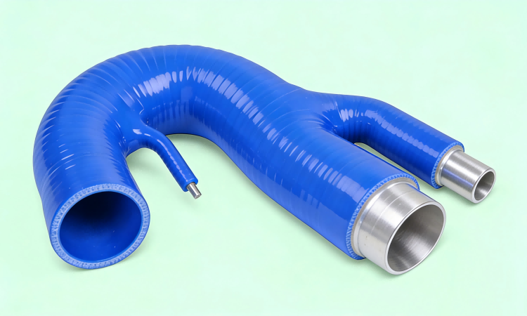
High Performance Air Intake Hose Engineering for Automotive & Industrial Engines
Air Intake System
1. Overview | Air Intake System Engineering Requirements
Air intake systems are responsible for delivering clean, stable and measured airflow into the engine combustion system.
Silicone air intake hoses are widely used in:
»Naturally aspirated engine intake systems
»Turbocharged and supercharged intake systems
»Cold air intake systems (CAI)
»Industrial engine air transfer systems
»Heavy-duty truck intake assemblies
Compared with traditional rubber hoses, silicone intake hoses provide:
»Higher temperature resistance
»Better deformation stability under vacuum
»Improved airflow consistency
»Longer service life under engine bay heat
2. Working Environment of Air Intake Systems
2.1 Temperature Conditions
Air intake hoses are exposed to both ambient and engine bay heat:
»Ambient air intake: -30°C to 50°C
»Engine bay temperature: 80°C – 150°C
»Turbo system inlet air: up to 180°C – 220°C (after compression heating near system components)
»Heat soak conditions after shutdown: up to 200°C localized exposure
Engineering requirement:
High-quality silicone intake hoses support:
-60°C to 230°C continuous operating range
2.2 Pressure Conditions
Air intake systems operate under:
Naturally aspirated engines:
»Slight vacuum or near atmospheric pressure
»Pressure range: -0.2 to 0.2 bar
Turbocharged engines:
»Boost pressure range: 0.5 – 3.5 bar
»High-performance systems: up to 4.0 bar peak spikes
Key engineering issue:
»Hose collapse under vacuum (cold air intake suction)
»Hose expansion under boost pressure
»Air leakage affecting AFR (air-fuel ratio stability)
2.3 Flow & Dynamic Stress
Air intake hoses must handle:
»High airflow velocity (especially turbo inlet)
»Pulsating airflow from throttle body
»Engine vibration and movement
»Pressure wave reflection in intake piping
3. Silicone Air Intake Hose Engineering Design
3.1 Material System
High-performance intake hoses use:
»VMQ high-temperature silicone rubber
»Optional fluorosilicone inner layer (for oil mist resistance)
»UV and ozone resistant additives
»Anti-aging stabilizers for long engine bay exposure
Key benefits:
»No hardening over time
»Stable flexibility in hot/cold cycles
»Excellent environmental resistance
3.2 Reinforcement Structure
Air intake silicone hoses typically use:
»1–2 ply → low-pressure intake systems
»3 ply → standard automotive intake systems
»4 ply → turbocharged intake systems
»5 ply → high-boost performance systems
Engineering function:
»Prevent vacuum collapse
»Maintain structural integrity under boost
»Reduce hose deformation under airflow pulsation
»Improve sealing at clamp joints
3.3 Wall Structure & Flow Stability
Engineering design focuses on:
»Smooth inner surface (reduced turbulence)
»Uniform wall thickness
»Controlled flexibility for tight engine bay routing
»Reinforced bead connection zones
4. Technical Performance Data
| Property | Rubber Intake Hose | Silicone Intake Hose |
|---|---|---|
| Temperature Range | -40°C to 120°C | -60°C to 230°C |
| Vacuum Resistance | Medium | High |
| Boost Resistance | Medium | High |
| Aging Resistance | Medium | Excellent |
| Flexibility | Degrades over time | Stable long-term |
| Service Life | 3–5 years | 5–10+ years |
5. Air Intake System Applications
5.1 Turbocharged Air Intake System
»Air filter to turbo inlet hose
»Turbo inlet pipe connection
»Compressor inlet ducting
Engineering focus:
»Vacuum collapse resistance
»Smooth airflow transition
»Reduced intake restriction
5.2 Cold Air Intake (CAI) Systems
»Filter relocation intake pipes
»Fender-mounted intake ducts
»Performance aftermarket intake kits
Engineering focus:
»Heat isolation from engine bay
»Stable airflow under high RPM
»Structural rigidity under vibration
5.3 Naturally Aspirated Engine Intake
»Airbox to throttle body hoses
»Resonator intake pipes
»OEM replacement intake tubing
Engineering focus:
»Stable airflow measurement
»No air leakage (MAF sensor accuracy)
»OEM fitment compatibility
5.4 Heavy-Duty & Industrial Intake Systems
»Truck engine intake ducts
»Construction machinery intake hoses
»Generator engine air systems
Engineering focus:
»Dust resistance
»Long-term durability
»High vibration endurance
6. Failure Modes & Engineering Solutions
6.1 Hose Collapse (Vacuum Failure)
Cause:
»Thin wall structure or low reinforcement
Solution:
»Multi-ply reinforcement (3–5 layers)
»Structural ribbing design for large diameter hoses
6.2 Hose Expansion Under Boost
Cause:
»Insufficient reinforcement strength
Solution:
»Aramid/Nomex reinforced fabric layers
»Controlled wall thickness design
6.3 Air Leakage at Connections
Cause:
»Poor clamp sealing or dimensional mismatch
Solution:
»Bead-rolled pipe ends
»T-bolt clamp system
»Tight tolerance manufacturing
6.4 Heat Aging & Hardening
Cause:
»Prolonged engine bay exposure
Solution:
»High-temperature VMQ silicone compound
»UV and ozone resistant formulation
7. Engineering Selection Guidelines
When selecting silicone intake hoses, engineers should evaluate:
»Engine type (NA / Turbo / Supercharged)
»Vacuum vs boost pressure conditions
»Hose diameter and airflow requirement
»Installation routing complexity
»Temperature exposure zone (hot side / cold side)
»Sensor integration (MAF/MAP compatibility)
8. HOTOP Engineering Capability
We provide OEM and custom silicone air intake solutions:
»Custom molded intake hose design
»Multi-diameter intake couplers
»Turbo inlet hose engineering
»Cold air intake system development
»OEM reverse engineering based on samples
9. FAQ
Q1: What is the temperature range of silicone air intake hoses?
Typically -60°C to 230°C, depending on formulation and reinforcement.
Q2: Are silicone intake hoses better than rubber hoses?
Yes. They offer better heat resistance, longer lifespan, and improved deformation stability.
Q3: Do silicone intake hoses improve performance?
They do not directly increase power, but improve airflow stability and reduce restriction.
Q4: Can silicone hoses be used for turbo intake systems?
Yes, reinforced silicone hoses (3–5 ply) are widely used in turbocharged intake systems.
10. Conclusion
Air intake systems require hoses that maintain stable airflow, structural integrity, and long-term durability under vacuum and pressure conditions.
Engineering-grade silicone intake hoses provide:
»Stable airflow performance
»High temperature resistance
»Vacuum collapse protection
»Long service life in engine environments
Copyright©2025 | Hotop Silicone Hose | Sitemap |